Hydrocal 1008 Offshore

DGA Sensor 8 outputs for corrosive environments

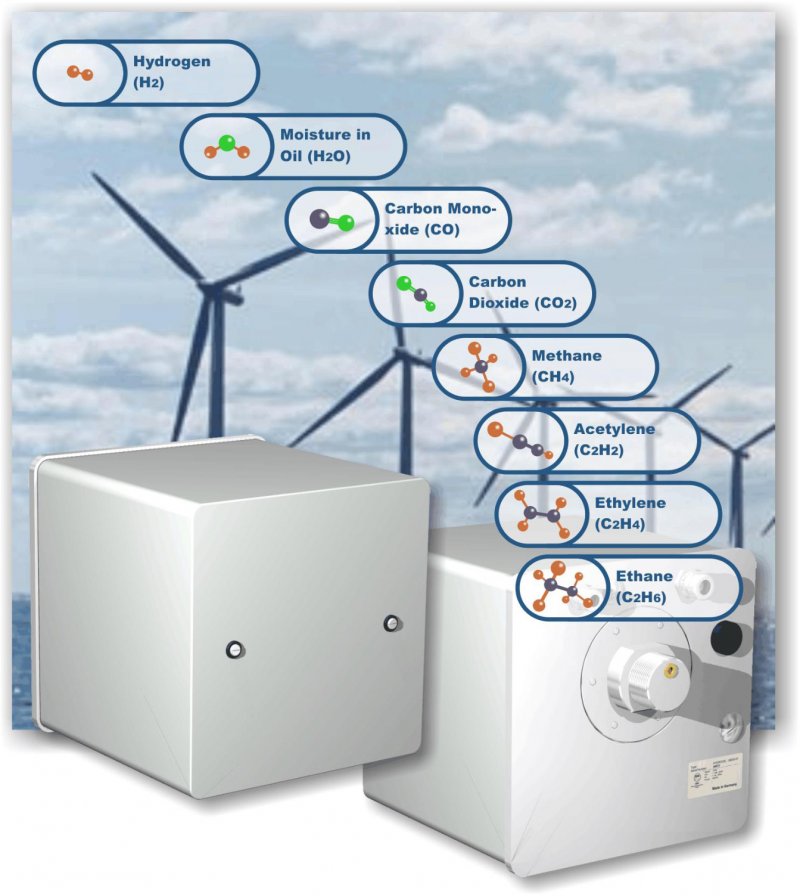
Online gas-in-oil measurement sensor Hydrocal 1008 Offshore, a system with 8 outputs for measuring:

  • H2 Hydrogen
  • CO Carbon Monoxide
  • CO2 Carbon Dioxide
  • CHMethane
  • C2H2 Acetylene
  • C2H4 Ethylene
  • C2H6 Ethane
  • H2O Moisture

Hydrocal 1008 Offshore 

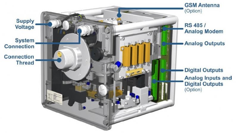
The HYDROCAL 1008 Offshore is a permanently installed multi-gas-in-oil analysis system with transformer monitoring functions:

It individually measures the most relevant gases dissolved in transformer oil, such as:

  • Hydrogen (H2)
  • Carbon Monoxide (CO)
  • Carbon Dioxide (CO2)
  • Methane (CH4)
  • Acetylene (C2H2)
  • Ethylene (C2H4)
  • Ethane (C2H6)

Furthermore, it measures moisture (H2O) present in dielectric oil.

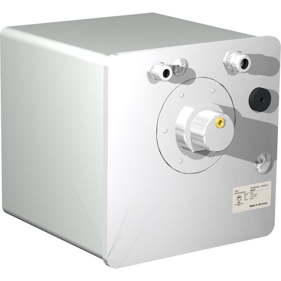
The HYDROCAL 1008 Offshore is specially designed for the harsh conditions (saltwater, corrosion) on offshore platforms (e.g. offshore windmill parks). A special painted housing with no window and chrome-nickel and stainless steel application ensure the device's reliability and persistence.

The device can serve as a compact transformer monitoring system by the integration/connection of other sensors present on a transformer via its optional analog inputs:

  • 4 analog inputs 0/4 ... 20 mADC
  • 6 analog inputs 0/4 ... 20 mAAC +20% or 0 ... 80 VAC +20% (configurable by jumpers)

Hydrocal 1008 is further equipped with digital outputs for the transmission of alerts or the execution of control functions (e.g. control of a cooling system of a transformer):

  • 5 digital relay outputs
  • 5 digital optocoupler outputs (option)

Key Advantages
  • Individual measurement of Hydrogen (H2), Carbon Monoxide (CO), Carbon Dioxide (CO2), Methane (CH4), Acetylene (C2H2), Ethylene (C2H4) and Ethane (C2H6)
  • Moisture in oil (H2O) measurement
  • Special design for offshore applications:
  • Housing without window painted in C5M
  • Backplate with cable glands (chrome-nickel steel, IP 68, corrosion-free and acid-resistant)
  • Backplate, oil entrance and housing screws made of stainless steel V4A
  • Easy to mount on a transformer valve (G 1½" DIN ISO 228-1 or 1½" NPT ANSI B 1.20.1)
  • Installation on the operational transformer without any operational interruption
  • Advanced software (on the unit and via PC)
  • Maintenance-free system
  • Communication interfaces ETHERNET 10/100 Mbit/s (copper-wired / RJ 45 or fibre-optical / SC Duplex) and RS 485 to support MODBUS®RTU/ASCII, MODBUSÒTCP, DNP3 proprietary communication and IEC 61850 protocols
  • Optional 2G/3G modem with external adhesive antenna
  • Optional DNP3 serial modem for SCADA connection
  • Optional IEC 61850 modem for SCADA connection
  • Optional HV and LV bushing sensors for HV and LV bushing monitoring applications via communication interface

Transformer monitoring functions

The Hydrocal 1008 Offshore can be used as a complete monitoring system for the condition of the transformer. The main monitoring options are listed below:

Voltages and currents
  • via voltage and current transformers/transducer
Temperature Monitoring
  • Bottom and top oil temperature, ambient temperature (via additional temperature sensors)
Cooling Stage / Tap Changer Position
  • (e.g. via current transducer)
Free configuration
  • Analog inputs can be free allocated to any additional sensor
Further calculations:
  • Hot-Spot
  • Loss-of-Life
  • Ageing Rate
HV and LV Bushing monitoring functions (option)

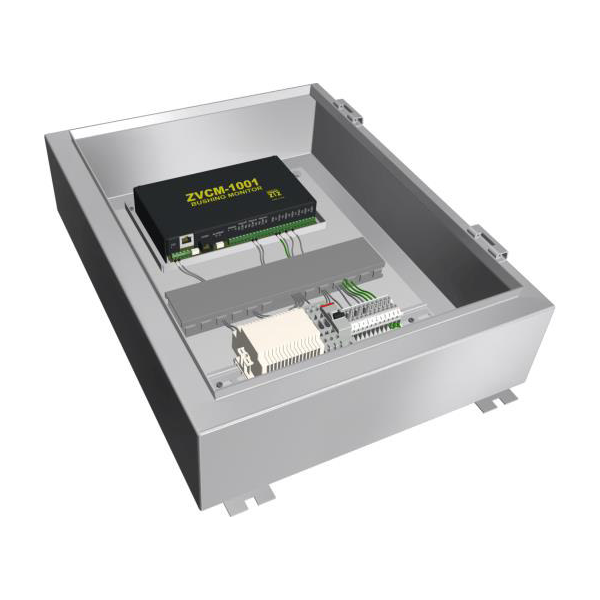
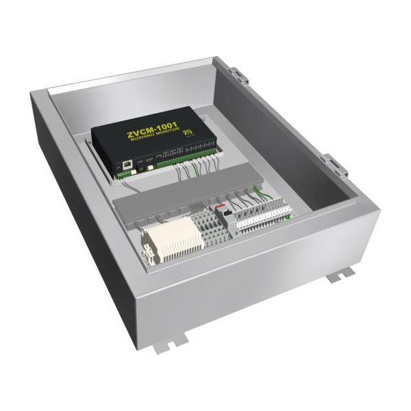
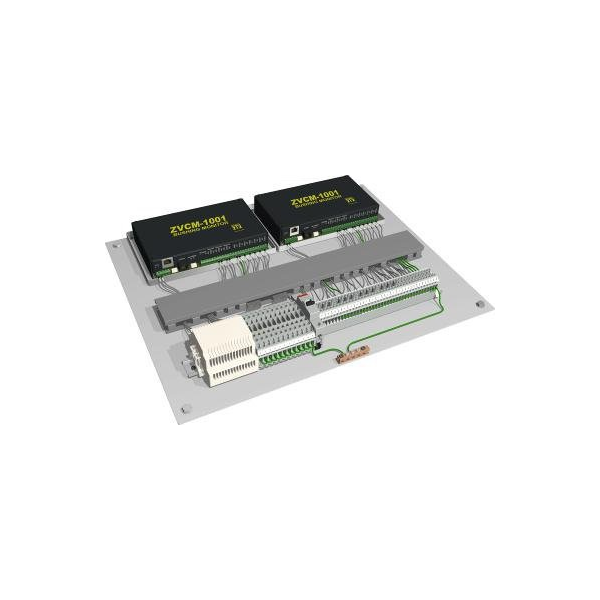
The Bushing Monitoring system simultaneously monitors the bushing leakage current of two rows of three-phase groups of bushings. The system incorporates three different measurement modes on each tested component to provide accurate power factor and capacitance values to evaluate the condition of bushing insulation.

The measurement modes are the following:

  • Phase comparison: Compares the power factor of tested components with other tested components energised with the same phase voltage.
  • Sum of three current tests: Measures the imbalance current from the summation of A, B and C phase currents from three tested components such as the three HV or LV bushings on the transformer.
  • Adjacent phase reference test: Compares the power factor of the tested components with other phase components on the same equipment.

The bushing sensors/adapters are connected to the capacitor taps designed for all bushings to allow measurement of the leakage current up to 140 mA. The adapters are designed for bushings with grounded and undergrounded capacitor taps. The adapter is designed to prevent voltage from developing if the sensor is disconnected from the Bushing Monitoring system.

High and low voltage monitoring

Different bushing sensor configurations are possible:

  • Monitoring of high-voltage side
  • Monitoring of high- and low-voltage side
  • Reference HV bushing from other transformers
  • Reference CCVT / CCPT

 Configuration with 3, 6, 9 or 12  bushing sensors is possible.

HydroSoft PC-Software
Program key features
  • Configuration and administration of each HYDROCAL unit
  • Data and configuration readout of HYDROCAL units
  • Processing and presentation of data readout (trend or table)
  • Online functions (online sensors, extraction status and process flow)
  • Diagnostic functions (Duval triangle and Rogers 3D graphic)
  • Further processing of the processed data (Excel, CSV, clipboard and printing)
  • Storage of the processed data and unit configuration
Key Features
  • 230V AC or 110V DC supply
  • Connection to valve: NPT 1” ½ or DIN-ISO 1” ½
  • Degree of protection: IP55
  • 5 digital relay outputs (220 VDC/VAC / 2 A / 60 W)
  • 5 current DC 4-20 mA
  • Communication: RJ45 RJ 45 or multimodal fiber-optic with SC Duplex (ETHERNET or MODBUS® TCP protocol)
  • Version suitable for corrosive environments painted C5M, V4A stainless steel and IP 68 chrome-nickel cable glands, corrosion-free and acid-resistant
Operation principle
  • Miniaturised gas sample production based on headspace principle (no membrane, negative pressure proofed)
  • Patent-pending oil sampling system (EP 1 950 560 A1)
  • Near-infrared gas sensor unit for CO, C2H2 and C2H4
  • Near-infrared gas sensor unit for CO2, CH4 and C2H6
  • Micro-electronic gas sensor for H2
  • Thin-film capacitive moisture sensor H2O
  • Temperature sensors (for oil and gas temperature)
Technical Data

Optional nominal voltages of auxiliary supply

120 V -20% +15% AC 50/60 Hz
230 V -20% +15% AC 50/60 Hz
120 V -20% +15% DC
230 V -20% +15% DC

Power consumptionMax. 600 VA
HousingAluminum with painting C5M / stainless steel V4A
DimensionsW 263 x H 274 x D 312 mm
Weightapprox. 18 kg
Operation temperature (ambient)-55°C ... +55°C (below -10°C display function locked)
Oil temperature (inside transformer)-20 °C ... +90 °C
Storage temperature (ambient)-20 °C ... +65 °C
Oil pressureUp to 800 kPa (negative pressure allowed)
Connection to valve:G 1½" DIN ISO 228-1
1½” NPT ANSI B 1.20.1
SafetyCE certified
Insulation protectionIEC 61010-1:2002
Degree of protectionIP-55
Analogic Outputs
TypeRangeDefault concentration (Free assignment)
1 Current DC0/4 ... 20 mA DCHydrogen H2
1 Current DC 0/4 ... 20 mA DCAcetylene C2H2
1 Current DC 0/4 ... 20 mA DCEthylene C2H4
1 Current DC 0/4 ... 20 mA DCCarbon Monoxide CO
1 Current DC0/4 ... 20 mA DCMoisture H20
1 Current DC0/4 ... 20 mA DCCarbon Dioxide CO2
1 Current DC0/4 ... 20 mA DCEthane C2H6
1 Current DC0/4 ... 20 mA DCMethane CH4
Digital output
TypeControl voltageMax. Switching capacity (Free assignment)
8 Relay12 V DC220 V DC / V AC 2A / 60 W
Communication
RS 485 (proprietary or MODBUS® RTU/ASCII protocol)

ETHERNET 10/100 Mbit/s modem copper-wired / RJ 45 or fibre-optical / SC Duplex (proprietary or MODBUS® TCP protocol)

2G/3G modem with external adhesive antenna (Option) (proprietary protocol)
DNP3 serial modem (Option) with RS 485 connection (DNP3 protocol)
IEC 61850 modem (Option)

Products Gallery

Service

For any information you can contact us by phone or e-mail:
+39 0471 1800338 -

There are no articles in the shopping cart